 |
|
|
|
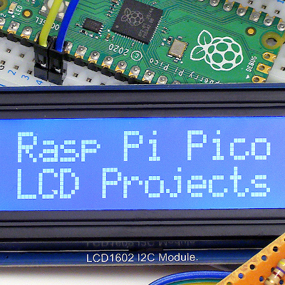
Raspberry Pi Pico LCD Projects
Below are links to the code, as well as the wiring diagrams, featured in this video. For the anemometer, please also see this page. Wiring for connecting the LCD module to the Pico:  Wiring for connecting the switch module to the Pico. This wiring is in addition to the above for the LCD module. And note that, because I had the Pico in a breadboard, my VCC connection was actually to a rail on down the side of the breadboard, to which I had connected pin 36 (3.3V OUT):  Wiring for connecting the reflective IR sensor to the Pico. Again note that, due to the use of the breadboard, some of my wiring was indirect, and that I ahd the resistors on a breakout board, as this is what I had constructed in my first anemometer build, as linked above: 
Return to: Videos Homepage.
|
 |
|
| ||